- 您现在的位置:买卖IC网 > Sheet目录394 > ANT-1356M (RF Solutions)ANTENNA RFID COIL 13.56MHZ
�� �
�
�ib� technology�
�2)� The� Micro� RWD� is� designed� to� generate� a� 13.56� MHz� carrier� frequency� in� short�
�bursts� of� energy� with� a� peak-to-peak� voltage� of� up� to� 60� volts.� This� RF� field� is� only�
�turned-on� whenever� there� is� card� communication� and� for� the� remainder� of� time� the�
�RF� field� is� off.� This� dramatically� reduces� the� average� current� consumption� to� around�
�20ma� with� short� bursts� of� up� to� 200ma.�
�3)� Generally� for� 65mm� diameter� wound� antenna� or� similar� sized� PCB� antenna� the�
�range� is� around� 5� cm,� larger� antenna� (10� –� 15cm� diameter)� can� achieve� up� to� 10cm�
�range� under� ideal� conditions.� Lower� burst� current� can� be� achieved� by� adjusting� the�
�series� resistors� in� the� antenna� loop� circuit� (ensuring� Q� value� is� around� 35-40).�
�4)� Sample� antenna� supplied� are� for� evaluation� only.� The� characteristics� of� an� antenna�
�for� EMC� approval� will� vary� according� to� shape� of� coil,� type� of� wire,� style� of�
�winding,� bobbin� material,� spacing� between� windings� or� PCB� track� design� and� PCB�
�material� etc.�
�5)� The� antenna� coil� (PCB� or� wire� wound)� should� be� positioned� as� close� to� the� capacitor�
�components� as� possible� and� the� coil-capacitor� (LC)� arrangement� should� be� no� more�
�than� 3cm� from� the� MicroRWD� module� for� optimum� performance.� For� longer�
�distances� a� screened� twisted-pair� antenna� cable� can� be� used� with� an� impedance�
�matching� transformer,� this� technique� is� not� described� here.�
�6)� The� position� and� environment� of� the� antenna� in� the� final� applications� should� be�
�taken� into� account� and� a� trimming� capacitor� can� be� used� to� adjust� the� capacitance� to�
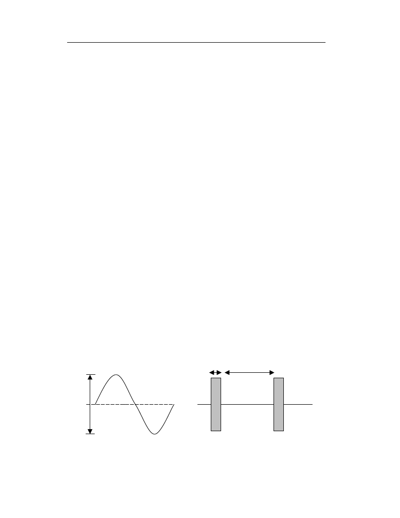
�fine� tune� the� LC� arrangement� back� to� 13.56� MHz� resonance.� An� oscilloscope� should�
�be� connected� ACROSS� the� antenna� coil� connections.� With� NO� transponder� card� in�
�the� field� a� pulsed� 13.56� MHz� sine� wave� will� be� seen� with� a� peak-to-peak� voltage� of�
�up� to� 60� volts.� The� trimming� capacitor� should� be� adjusted� to� achieve� the� highest�
�amplitude� of� sine� wave.� The� antenna� resistance� should� then� be� checked� to� ensure� the�
�Quality� factor� is� correct.� The� capacitor� and� coil� inductance� values� have� been�
�carefully� chosen� for� optimum� performance� so� any� custom� antenna� should� be�
�designed� to� be� as� close� to� this� arrangement� as� possible.�
�Antenna� waveform�
�13.56� MHz�
�7.5� ms�
�100ms� (default� polling� delay)�
�60v� peak-to-peak� measured�
�NO� card� in� field� –� RF� duty� cycle�
�across� the� antenna� coil�
�NOTE� THAT� OPTIMUM� PERFORMANCE� (BEST� SIGNAL� TO� NOISE� RATIO)� IS� ACHIEVED�
�WHEN� PEAK-TO-PEAK� ANTENNA� VOLTAGE� IS� APPROXIMATELY� 50� VOLTS.�
�2�
�发布紧急采购,3分钟左右您将得到回复。
相关PDF资料
AO3460
MOSFET N-CH 60V .65A SOT23-3
AO4407A
MOSFET P-CH -30V -12A 8-SOIC
AO4438
MOSFET N-CH 60V 8.2A 8-SOIC
AO4447A
MOSFET P-CH 30V 17A 8-SOIC
AO4496
MOSFET N CH 30V 10A SOIC 8
AO5803E
MOSFET 2P-CH 20V 0.6A SC89-6L
AO6808
MOSFET 2N-CH 20V 4.6A 6TSOP
AO7410
MOSFET N-CH 30V 1.7A SC70
相关代理商/技术参数
ANT14
制造商:CIT 制造商全称:CIT Relay & Switch 功能描述:CIT SWITCH
ANT1400F
制造商:RCA 功能描述:Passive Multi Directional Flat Digital Antenna - White 制造商:RCA 功能描述:INDOOR ANTENNA FLAT PANEL WHITE
ANT1400R
制造商:RCA 功能描述:Passive Multi Directional Flat Digital Antenna - White 制造商:RCA 功能描述:INDOOR ANTENNA FLAT PANEL WHITE
ANT1450BF
制造商:RCA 功能描述:RCA Low Profile Antenna UHF/DTV/HDTV Active 制造商:RCA 功能描述:RCA LOW PROFILE ANTENNA UHF/DTV/HDTV ACTIVE BLACK
ANT1450BR
制造商:RCA 功能描述:RCA Low Profile Antenna UHF/DTV/HDTV Active 制造商:RCA 功能描述:RCA LOW PROFILE ANTENNA UHF/DTV/HDTV, ACTIVE, BLACK
ANT15
制造商:CIT 制造商全称:CIT Relay & Switch 功能描述:CIT SWITCH
ANT1515B00FT1575A
功能描述:天线 1580+/-2MHz 50 Ohm PATCH ANTENNA,GPS
RoHS:否 制造商:Molex 技术类型:Cellular Antenna 频率: 带宽: 尺寸:106.7 mm L x 13 mm W
ANT1515B00FT1575S
功能描述:1.6GHz GPS Ceramic Patch RF Antenna 1.576GHz ~ 1.584GHz 1.5dBic Pin Surface Mount 制造商:yageo 系列:- 包装:托盘 零件状态:有效 频率组:UHF(1 GHz ~ 2 GHz) 频率(中心/带):1.6GHz 频率范围:1.576GHz ~ 1.584GHz 天线类型:陶瓷贴片 频带数:1 VSWR:2 回波损耗:-10dB 增益:1.5dBic 功率 - 最大值:- 特性:- 端接:引脚 侵入防护:- 安装类型:表面贴装 高度(最大值):0.177"(4.50mm) 应用:GPS 标准包装:70